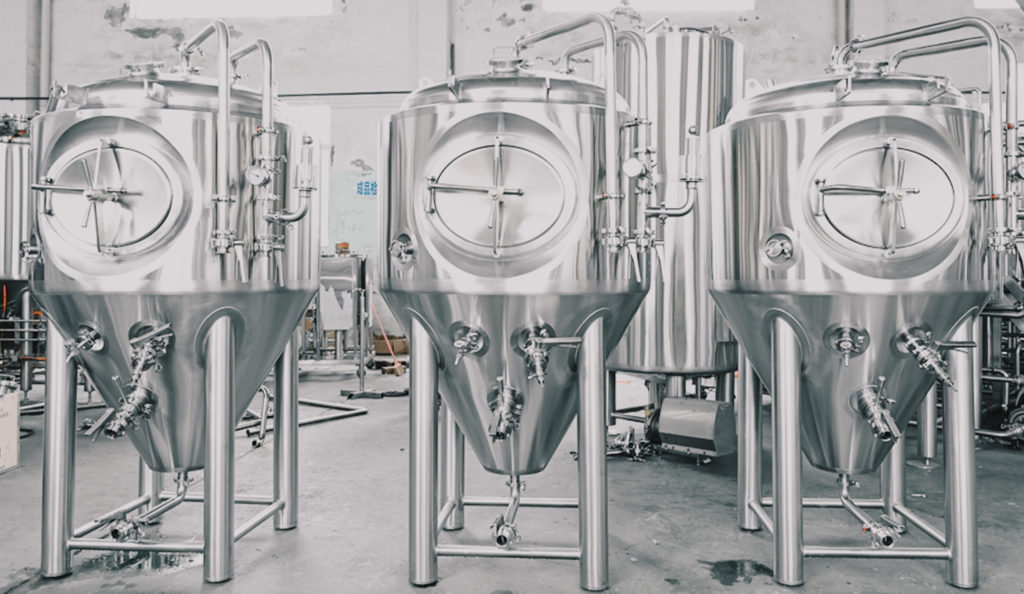
Fermentation Vessels, or FVs for short, are vital for breweries of all sizes. Some might say this is where all the magic happens!
We design our FVs to produce quality beer, but also fit your space and include the components and design features to help make your life easier. A seamless process, from installation all the way through to fermentation is our goal.

Our Bespoke Design Process
Our design process is where we really get to live up to our name. Following the Bespoke Way, we go through a detailed design process with our clients to ensure our equipment fits their exact needs.
Each client starts their Bespoke journey with an Overview File which contains the key information for a project such as billing information, shipping information, project folder links, manufacturing completion targets, etc. We use Google Sheets for hosting these files and can share them with clients so they can access and edit them at any time.
Also within this file, we have tabs for the main vessels typically ordered and FVs are at the top of that list. In each tab, we have put together a pretty extensive list of the design features, options, and components to consider when designing your FVs. You can access a read-only version of this sheet via the below link:
DOWNLOAD AN EXAMPLE OF OUR OVERVIEW FILE
Typically, one of our sales team members will schedule a Zoom call to either go line by line with a client and build their FVs or for those overachieving clients, review what they have inputted in the sheet themselves to make sure there is not any confusion.
Once confirmed we pass this on to the project manager who coordinates with the CAD team on getting these requirements into a 2D drawing for review and subsequent approval.
Below, we will walk you through all of the design elements for Fermentation Vessels and their possible configurations:
We start with what we call Dimensions. These impact the overall size and shape of the vessel and are critical to have rock solid. These include:
Working Capacity: The capacity which you are aiming for after fermentation is complete.
Head Space: The percentage of extra head space in the vessel and our standard is 25%.
Full Capacity: The working capacity plus headspace percentage. For example, a 1000L vessel with 25% headspace would have a full capacity of 1250L.
Cone Angles: The angle of the cone on the FV. Our standard is 60 degrees, but in situations where height might be an issue, we have increased this to 70 degrees to get more to decrease the height by fitting more volume in the cone.
Working Pressure: The max working pressure of our FVs can be determined by our clients’ requirements. The standard is 1 bar (15 psi), but with unitanks, we will raise it to 2 bar (30 psi). From confirmation of working pressure, the production team will then set the design pressure and pressure test accordingly up to 0.8 bar (11psi) above the working pressure. We then set our PRVRs to release to the confirmed working pressure figure.
Max Height: We consider this the max height of the tallest part of the FV, which is usually the top of the CIP arm. Note that with top manway vessels, the manway will exceed the height of the CIP arm when open.
Max Outside Diameter: This is the max outer diameter or OD of the vessel.
Brewery Standard Fitting: The standard fittings used in the brewery for connection hose to vessels. This is predominantly the ISO tri-clamp, but we have also worked with DIN and BSM/RJT.
Manway Location: This can either be top of side manway with our preference being top manways as you should not have to open the manway, especially if you have a nice hop port or, better yet, a hop cannon.
Insulation: We will typically use high-grade polyurethane (PU) foam, which is injected into the spacing between the inner and outer shell.
Insulation Thickness: For tanks that are less than or equal to 360L (3BBL), we will use 50mm of insulation, 80mm of insulation on tanks larger than 360L (3BBL), and 100mm for 9600L (80BBL) tanks.
Ladder Hooks: These are the hooks on the vessel which you can hang a ladder from. It is standard that We will include on tanks taller than 2000mm (6.5’).
Lifting Lugs: These are the lifting lugs, which can be used to stand the vessel up. They are designed to handle the dry weight of the vessel. Our standard is 2 lifting lugs per vessel.
Number of Legs: Our standard number is 4, but depending on the weight rating of the floor, we can add more to help spread the weight out.
Detachable Feet: Our tank feet come in 2 pieces as you have the foot screw and plate. You screw the foot screw into the leg and can adjust the height of each leg, which is handy if there is a slant on the floor. The screw then sits on the plate, but allows for the plate to be slightly angled to follow the slope of the floor.
Foot Plate: The Foot Plate diameter is determined by the dimensions of the FV, and the diameter of the vessel legs. We can increase the Foot Plate size to accommodate for load bearing, and can also add bolt holes for securing tanks in high seismic activity areas.
Adjustable Foot Range: This is the length of thread that the foot screw has, as this will determine the amount of range you have for the height of the vessel. This is critical as you want to make sure you have enough range to cover the slope of the floor.
Number of Jackets: The number of jackets you’d like for the vessel to have. This is usually 2 for smaller tanks and up to 4 for larger ones. You usually want to size your jackets to match the different batch sizes you might do so you could do ½ or ¾ batches in a larger tank.
Internal Looping: If you would like multiple jackets but only single or dual in/outlets, jackets can be linked with piping inside the insulation wall.
Termination Location: The termination point of the jacket inlets and outlets. We have really started to give clients a number of options to help save space, time, and money during installation. They can terminate on the side of the vessel or lately, we have been sending most tanks with them terminating at the top of the vessel and running the glycol lines in the insulation.
Birdseye Positioning: This is very important as you need to think about the best location with the least amount of obstructions. In our drawings, the manway is usually considered 0 degrees and we express a position in degrees.
Quantity: Typically, only one thermowell is needed, but for larger tanks, we have included up to 3 in various levels along the vessel.
Type: Our thermowells are welded into the inside of the tank and are polished to a sanitary finish. We have also purchased and installed from component manufacturers like IFM so clients could use their own RTDs.
Installation Angle: Thermowells can be installed either in parallel orientation or have a slight angle upwards or downwards to assist the cleaning chemicals to run off the probes.
Thermowell #1 Location: The most common place to find a thermowell on an FV is right above the line where the body and cone of the vessel meet.
Thermowell #2 Location: For your larger tanks, you might want a thermowell between the middle and top jacket.
Thermowell #3 Location: For larger tanks, we have put up to 3 thermowells in the tank so an operator can either check for stratification or operate a glycol valve if needed. Understanding the different zones of an FV is critical as your vessels get bigger.
Birdseye Positioning: This depends on where your cellar control panel will be as you want to keep the run as short as possible. Also, having clearance behind thermowells is important as you will need to remove them and they can be long.
Glycol Piping Required: Glycol piping can be provided internally or externally attached to the tank. The piping can include valves and componentry and be fixed with tri clamps saving you time and hassle during installation.
Internal/External: Internal piping provides better aesthetics for FV overall if the tanks are in view of the clientele. Also provides an easier connection to the main glycol loop as components can be connected directly to in/outlets. External piping can be provided for ease of installation and you only need to insulate once pressure/leak checks have been completed.
Pipe Size: Our standard pipe has an OD of 32mm and ID of 28mm.
Termination (In/Outlet) Location: Standard termination points are on the cone/side of the vessel. Angles for ports can be roughly 135°, 180°, and 225°.
Piping Birdseye Positioning: If you choose tank top termination ports, we will normally bring these to the 180° mark. Tank sides are also 180° as standard. However, these can be configured to what works best for your glycol pipework installation.
Connection Manifold Diameter
Location: We like PRVRs out of the way on the top of the tank although you can also install them on the vent or blow off the arm.
Birdseye Positioning: Originally we would put them at the back of the tank but quickly realized that having them accessible from the front where ladder hooks might be is the best way for inspection or removal.
Connection Size, Standard, and Type: Our standard would be a 2” ISO tri-clamp so you have the increased surface area for the valve.
Sprayball Type: Our standard FV configuration includes a rotating spray ball, but we also have static spray balls, usually used on smaller tanks and liquor tanks. We can also source cleaning heads from other suppliers to fit your needs or requirements.
Tank Inlet Connection Size & Standard: The tank inlet connection for the spray ball is on a 4” tri-clamp. This can also be a DIN thread if requested.
Pipe Size: The standard is 1.5” and has been enough to satisfy the requirements of our sprayballs to achieve a good cleaning radius.
Birdseye Positioning: The CIP port is directly in the center of the vessel (>250L)l. The CIP arm can straddle the manway on either the left or right side of the vessel. For smaller vessels, the arm enters the vessel on the angle of the formed head.
Connection Size & Standard: Our standard connection type is a 1.5” ISO tri-clamp, however, we have built customized tanks for different parts of the world that include SMS, DIN 11850, and even RJT.
Pipe Size: Acting as a dedicated vent/breathing arm during fermentation, our standard pipe size is 1.5”. For larger cellar tanks (>100hL) we can increase the bore of the pipe as required.
Birdseye Positioning: Can either be on the adjacent or opposite side to the CIP arm.
Connection Size, Standard, and Type: Our standard connection type is a 1.5” ISO tri-clamp, however, we have built customized tanks for different parts of the world that include SMS, DIN 11850, and even RJT.
Birdseye Positioning: You will usually want this on the front of the tank where there the best access is as you will usually be on a ladder or scissor lift when dry hopping. Of course, if you don’t want the hassle of this and possibly increased oxidation, reach out to one of our team members about a hop cannon.
Recirculation Tangent: We have had a client who utilized a tangential inlet on the side of the vessel with either a butterfly valve or one-way as a way to circulate the tank during dry hopping.
Handle & Chain on Cap: As a safety precaution, we add a handle and a chain to the dry hop port cap. This is useful so you do not drop the cap while dry hopping.
Connection Size, Standard, and Type: Our most common configuration is a 4” ISO tri-clamp with a handle. We have gone to 6” dry hop ports for some clients and even attached a chain to the clamp so it doesn’t fall. As an upgrade, we offer a DIN 11850 with the same chain so you don’t lose the cap.
If you really want to upgrade we can supply a 200mm/8” small pressurized manway or add on a hop bomber that can connect to the tri-clamp or DIN fitting.
Radar Level Detect Port: We have had clients install radar-level sensors into tanks to help check real-time volumes. The port is usually a proprietary mounting adaptor from the sensor manufacturer. The disadvantage to this is that during fermentation the reading will not be accurate due to krausen.
Type: Radars are a sanitary way of measuring the level of a tank without the extra CIP of a sight tube or glass and being next to the tank. We have used Krohne, IFM, and Vega radar-level sensors in the past with each having its own benefit with respect to price and function.
Birdseye Positioning: This is the positioning of the fitting in relation to the circular angle of the vessel.
Pressure Sensor Port: Pressure sensors are a sanitary way of measuring the pressure in the vessel without worrying about being next to the tank and maintaining a pressure gauge. The port is usually a proprietary mounting adaptor from the sensor manufacturer.
Type: We have used IFM sensors in the past, but most pressure sensors are similar in style and it really comes does to positioning and requirements.
Birdseye Positioning: This is the positioning of the fitting in relation to the circular angle of the vessel.
Pipe Size: For tanks that are less than or equal to 600L (5BBL), we will use a 1.5” pipe and increase to a 2” pipe or bigger for larger tanks. It is best to go bigger as it will prevent clogging as you are dumping trub.
Outlet Length: We will usually bring the pipe to the front of the vessel, but some brewers like only a 90-degree bend to avoid wort or beer from sitting in the line.
Connection Size, Standard, and Type: This is either an ISO 1.5” or 2” tri-clamp depending on if you’d like a reducer. We have also done DIN and RJT threads depending on the client and their location.
Reducer: If the drain is a 2” pipe then you will usually want an eccentric reducer at the end of the drain pipe so you can easily connect.
Type: We typically recommend a DIN65 thread for the racking arm to fit a 1.5” pipe. You can also use an ISO tri-clamp, but there is a risk of the clamp falling off while rotating the racking arm where a threaded connection is more secure. We have also started using racking arm assemblies which do not need to be loosened to rotate. They are limited to a 180-degree range, but that doesn’t matter too much. The port will also be on an angle as standard for better CIP capabilities.
Location: Always installed on the cone of the fermentation vessel, with the goal of the racking arm having the ability to get to the lowest point inside the tank possible.
Pipe Size: Our standard is 1.5”, but it can be increased. Increasing this pipe size will also increase the size of the connection to the tank and the external facing connection.
Target Draw Volume (Low): This is the low point on the racking arm when in the down position. This will dictate how much volume is left in the FV after racking.
Connection Size, Standard, and Type: The external facing connection at the racking arm is usually a 1.5” ISO tri-clamp.
Tangential inlets can be provided for use with dry hop or mixing equipment. Not a standard addition to a tank.
Location: Our standard location will be halfway up the body of the vessel.
Direction: These will be in a clockwise spin direction unless otherwise requested.
Check Valve: There will be a check valve next to the inlet.
Birdeye Positioning: Our standard location is on the opposite side of the CIP arm.
Connection Size & Standard: The external connection at the drop-down arm is usually a 1.5” ISO tri-clamp.
Location: Usually located at the base of the main body of the vessel. Can be placed on the cone if vessel dimensions are customized or if larger volume vessels.
Style: Perlick style valve as standard. Aseptic sample valves can be requested.
Birdeye Positioning: Normally 22°-33° to the left or right of 0°.
Connection Size & Standard: The external connection is usually a 1.5” ISO tri-clamp.
Location: Usually located at the base of the main body of the vessel. Can be placed on the cone if vessel dimensions are customized or if larger volume vessels.
Length and Width: Standard lengths are 300mm and range in two different ODs of 30mm and 40mm.
Birdeye Positioning: Normally 22°-33° to the left or right of 0°.
Connection Size & Standard: The external connection is usually a 1.5” ISO tri-clamp for the 30mm stone, however, for the 40mm stone it is a 2” ISO tri-clamp.
Location: Usually located next to either the sample valve or carb stone. Can be located wherever makes sense depending on what it will be used for.
The vertical location of the port with respect to the vert.
Birdeye Positioning: Can be placed at any position relative to the component being used.
Connection Size & Standard: The external connection is usually a 1.5” ISO tri-clamp.
Location: We recommend keeping pressure gauges on the CIP arm because then you can make sure you are reaching the target pressure for your sprayballs. You can also keep them on the blow-off arm along with the spunding valve.
Connection Size, Standard, and Type: Our preferred pressure gauges utilize a diaphragm adapter to make the system sanitary and connect to a 1.5” ISO tri-clamp.
Location: The BBS standard location of the spunding valve will be on the CIP arm if no vent arm is requested. If a vent arm is requested, we will move the spunding valve to the vent arm.
Connection Size & Standard: If a breathing arm is requested for your cellar tanks, as standard we will move the spunding valve off of the CIP arm. Pressure ratings of the spunding valve are from 0.2 – 2.2 BAR, and the standard connection type is a 1.5″ ISO tri-clamp. Speak to one of our team to see how we can include a dedicated stainless steel vent extension pipe, as part of the whole assembly.
Style: In some cases an FV will be used as a unitank and will be used for packaging so in this case you can put a sight tube on the tank so you can easily check volumes.
Location: Same as BBT. On drain outlet pipe and CIP arm for ease of CIP.
Connector for Dual CIP: If your FVs have CIP and blow-off arm on the same side of the tank. BBS can provide a connection piece to link these two arms together. This assists when running a CIP cycle, as you can clean both arms at once without removing the hose.
Tank Receival Manifold: The various inlets and outlets of an FV can be piped to a manifold which is used to make it easier to connect hoses to the tank and also use pipe jumpers to perform different tasks.
For more information on our Fermentation Vessels check out our Fermentation Vessels equipment page or get in touch with us.
Our team of brewing experts would love to help bring your craft beer project to life!


